30 January 2014

Left Lower Console - Part I

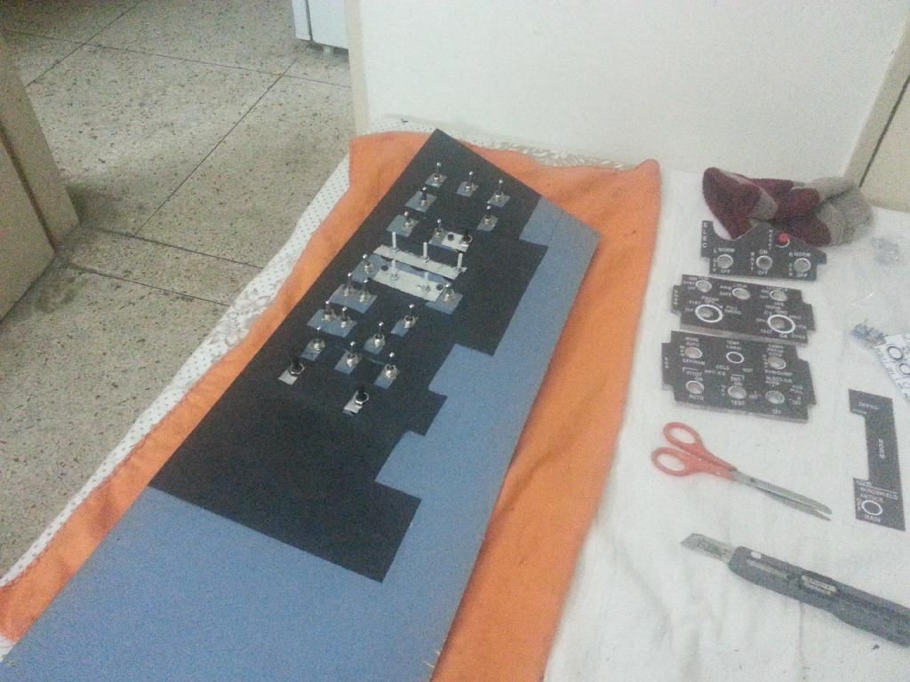
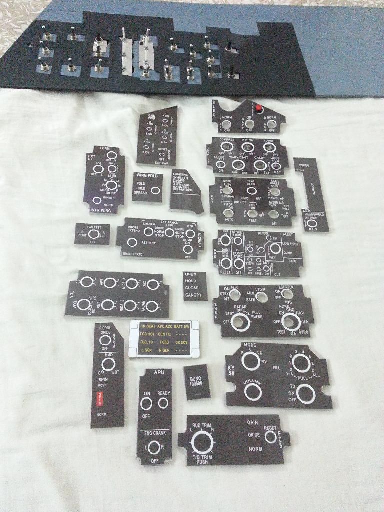
Getting all the panels placed correctly.

All the panels don't have switches. Yet! 

Ran out of the SPST/SPDT switches before I could complete all of them. Need to buy a few more, before I'm done with it.
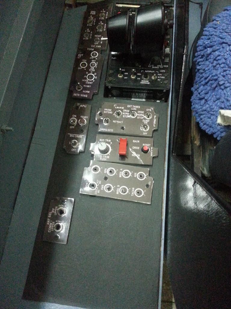
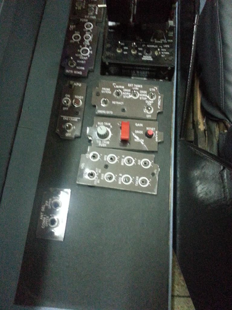
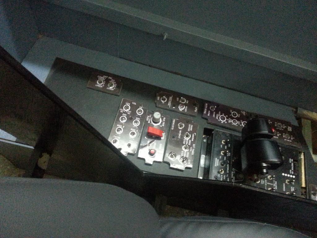
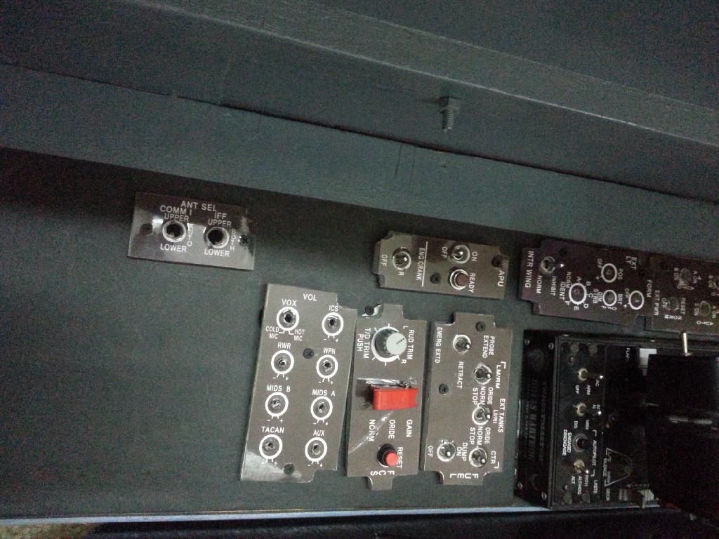
Now to start wiring up all the panels, and then to configure them for 'night lighting'.

06 January 2014

Right Lower Console - Part II

Through out the last week, I had been planning for the weekend. I was really really looking forward to finishing "all" my panels.

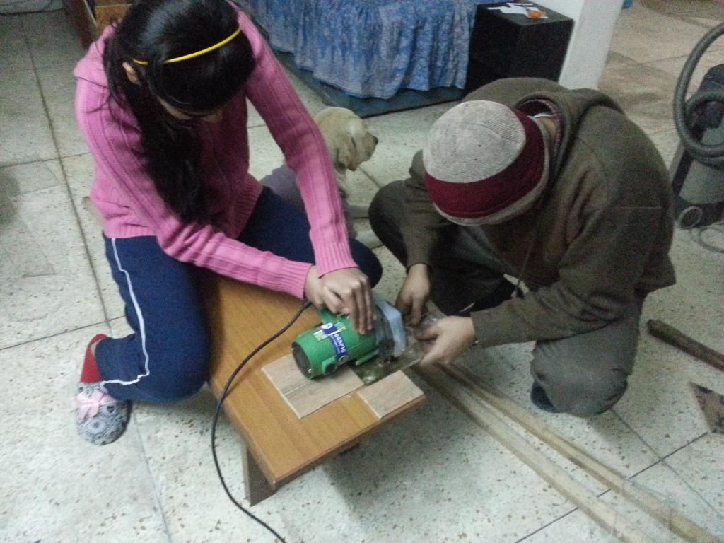
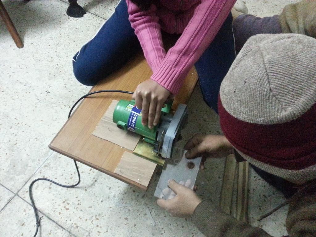
In the middle of the week itself, I had realized that in the limited time that will be available to me, I won't be able to accomplish the task with manual tools. So, I decided to invest in a power saw. 

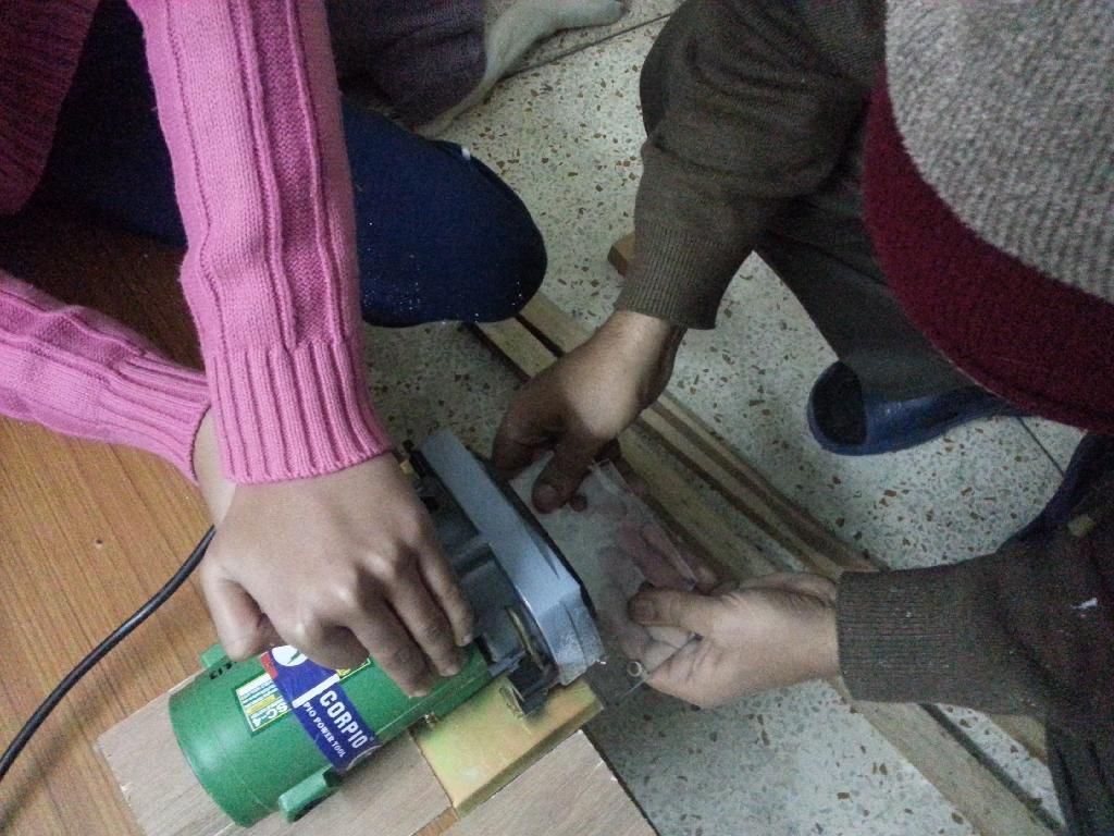
A little testing with the powered tool, and I realized that metal or wood cutting blades were not going to be very useful in cutting the plexiglass. Took advice of a friend, and purchased myself a "six-pack" of grinding blades. These blades are awesome. They cut through plexiglass like hot knife through a cake of butter.

Also realized, at some expense and wasted material, that while power tools are faster to work with, they also damage material equally fast. One has to really plan his cuts, to be able to accomplish reasonable level of finish. 

After the initial learning curve was over, by mid-Sunday, my daughter was equally comfortable using it, as I.


Cutting the big pieces was a lot easier, then shaping the small pieces. Most of the wastage happened in shaping the smaller pieces.

Finishing up the Right Lower Console. The black thick gauge paper is their to 'shape up the panel' in conformity with the actual airplane texture.
Two metallic pieces seen in the centre of the console are 'cut-out reinforcement'. Some switches (typically potmeters) were too thin, with smaller axles, that necessitated this arrangement.
The individual panel clusters are also beginning to shape up nicely.

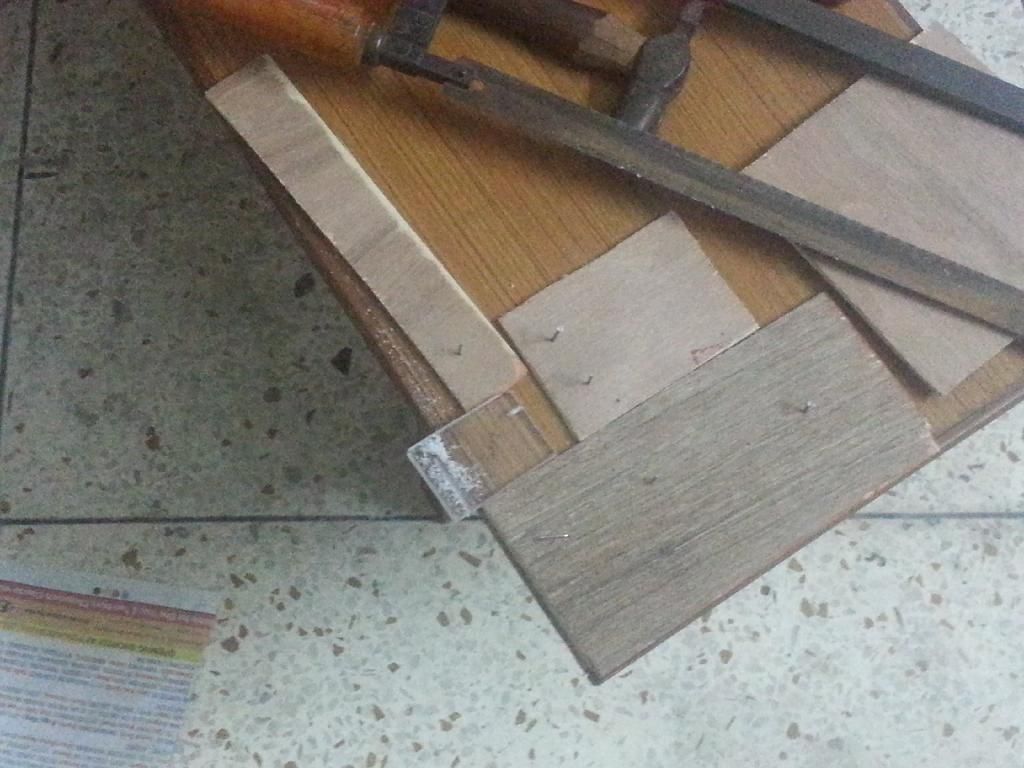
Not all 'cuts' can be made with a power saw. A lot of work had to be done with a manual hacksaw. Rigged up a temporary 'jig' to hold small pieces in place, while I made the cuts. Each of the three restraining pieces are rearranged for different pieces. While, I was doing this, I thought, I must take a picture of this 'local arrangement'. Who knows, someone else might find it useful. :)
I'm fairly happy with the end result 


More than two and a half days of back breaking work. And all I could finish was all the panels for Right Lower Console and a few panels for other instrument consoles. 

I'm thinking this is just about 40% of work accomplished. At this pace of work, it will take me atleast two more weekends to just finish the panels. Phew!!!

Did I mention, I did test out this panels for night lighting also. I forgot, or maybe I was too tired, but the results are quite amaz

28 December 2013

Right Lower Console - Part I


Been experimenting with building the "Left Lower Console" for the last few days. 

The reason I use the word 'experimenting' is because, till I started to 'cut' my panels, I was quite certain about the way I was going to build my panels. But, a related discussion with Wayne and Metro on "hornetpit" forums, have made me to review my plan. The complete discussion is at this thread (you will need to be logged in to view).

Anyways, what I have already achieved, is as per my original plan.


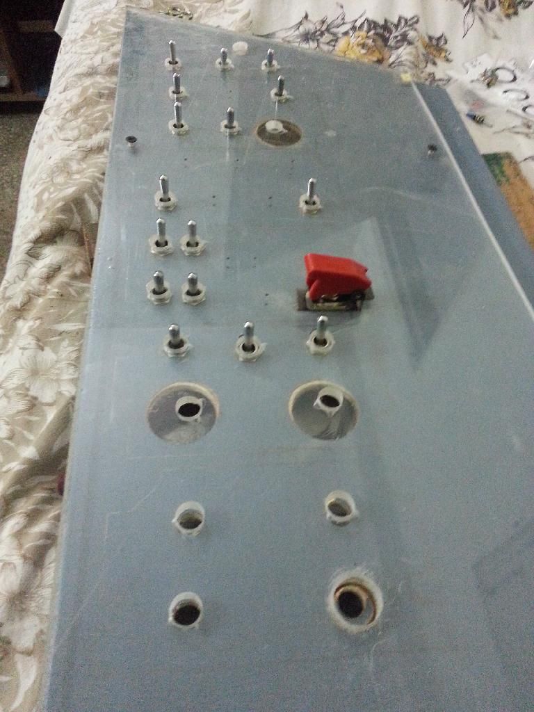
As per my original plan, the 5mm perspex sheet is intended to
overlay on the 5mm plywood base.
Theoretically, this planned looked nice, but, despite the overlay being a
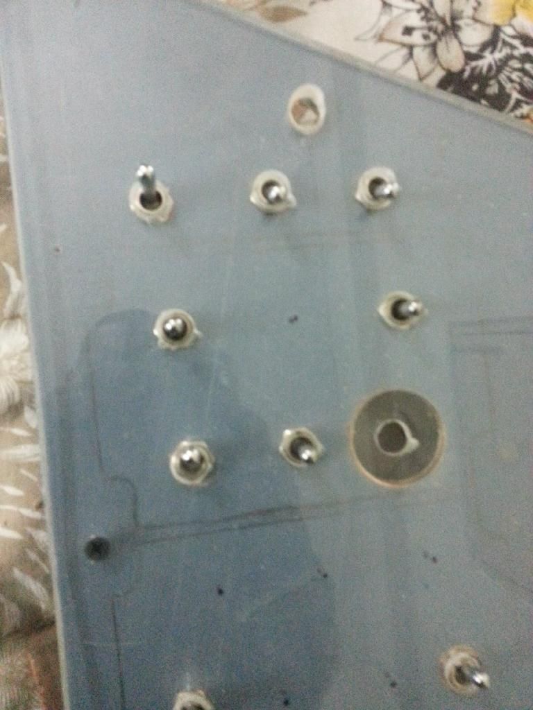
close fit, the switches appear to embed about 1-2mm below surface
of the perspex overlay. I'm not very pleased with that.
The 'largish' hole is to accommodate a single pole four way rotary switch 

It was at this point, that the discussion referred in aforementioned thread started, and I temporarily stopped further work with my panels. 

Initially, I experimented with a 'laser printed' overlay printed on a transparency, placed on top of the 5mm perspex sheet and testing out backlight. Too much of light passed through the overlay.

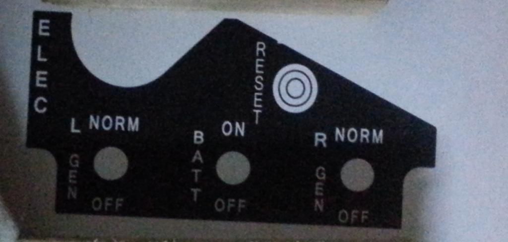
I then printed an experimental panel on a normal A4 sized paper as so.


All my pictures are taken on my mobile, since that is most handy while I'm working. This picture was taken in relatively poor light, so apologies for the poor quality. I have cropped the picture to remove unwanted detail.
Having printed on a plain paper, I overlayed this panel print on top of the perspex and placed LED lighting underneath. It still did not provide the desired effect. Too much of green light was still passing through. I could actually see each of the individual LEDs placed underneath.

I then doubled the number of perspex sheets and tested again. 


The effect was now rather pleasing. I'm thinking, when I print out the panel overlay on a professional grade paper, with a professional printing studio, the 'blacks' are going to be darker, and will prevent the the light that is still bleeding through. Disregard the LEDs that are visible on the extra white part of the panel. They are outside the limits of the panel.

The aim is to light up the 'text' on the panel, and the effect on backlighting the text is rather nice.

Now, off to redesign the complete console layout again. 

19 December 2013

UFCP - Part One

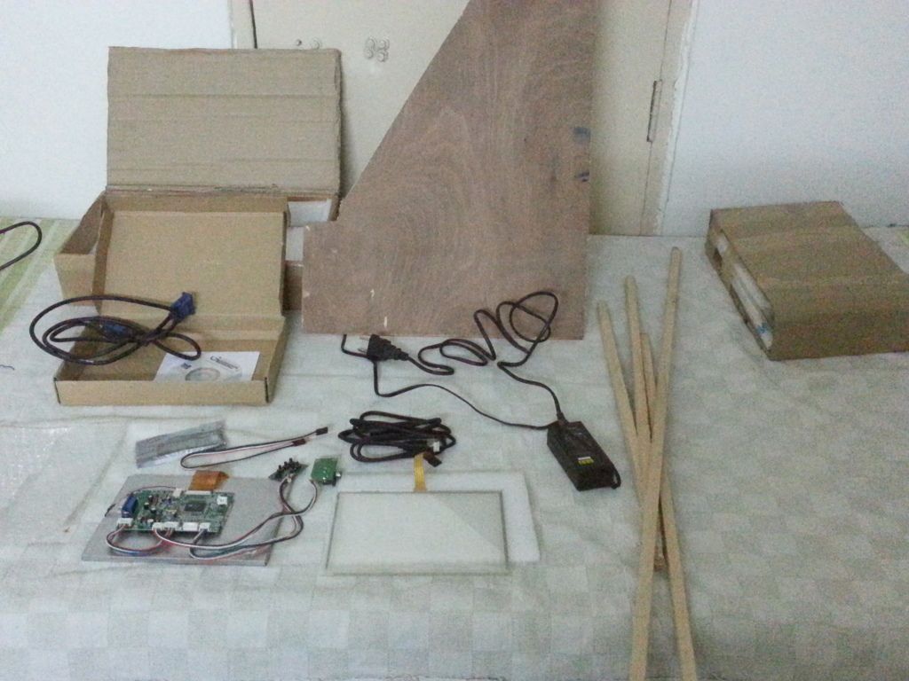
Started to fabricate my UFCP today. 

Initially, I hadn't anticipated that this is going to eat up so much of my time. After a couple of hours, I was still taking measurements and designing the shape, and counters, or the outer box. 

Eventually, I gave up the idea to work with wood/sheet metal directly. I will first experiment with a cardboard outer box, cut to correct dimensions. It's best to learn lessons from any mistakes on cardboard, before I proceed with a permanent fixture. 

I can already anticipate that, there will need to be 'slight' changes compared to the shape of the 'real one'. When viewed from side, the real UFCP has a taper from top to bottom. Also, the touch screen is inclined slightly downwards. For my pit, due to the type of touch screen I'm fabricating, I'm thinking, I will have to tilt it slightly upwards, if not keep it perfectly vertical. Let's see how it goes.

All the items I need to fabricate the UFCP. 

18 December 2013

First Test

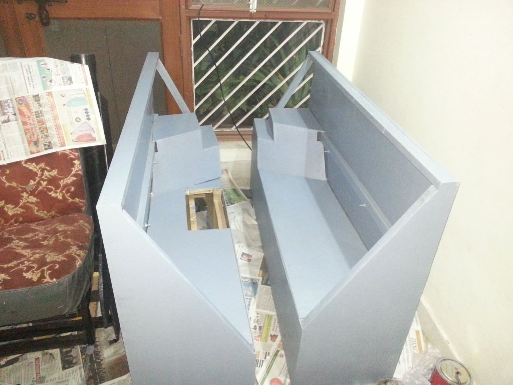
The last two days were busy in finishing up the major part of woodwork, including applying the second coat of paint to the superstructure of the pit.

I'm very happy that the major, labor intensive work of the pit is now behind me.

Started the day early today, to assemble the super structure and mate the flight-sim computer with the pit. There were a few areas of concern, but nothing that I couldn't take care of with a little work. 


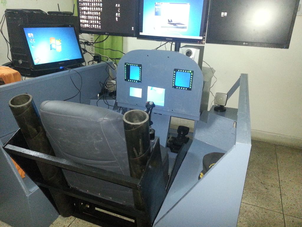
Assembled Pit
The seat if more or less done now, with new upholstery.
Two mock ejector tubes on the side.
Two more mock drogue tubes are pending fitment.

Despite all the tests, and final measurements, the seated leg length is a tad short. Will need to figure out how to work around that. I've full movement of rudder pedals available to me. However, I'm only able to apply about 75% brakes.
 
Firing Up the Computer for the First Time
Had to play a bit with screen resolutions and screen positioning in the nVidia tuning applet. Had to retune my nVidia Surround resolution also.

Not very happy with the positioning of the sub-woofer.
Will need to find another place for it.

The Triple-Monitor setup is about 4" too high. Need to bring it down a bit.

The 19" monitor on the side, looked okay till now. Till I didn't have a pit. Now, it's an eyesore. Will have to design a contraption, so that I'm able to position it above the Triple Monitor setup. But, that can wait for the time being.
There is other stuff to take care of first.


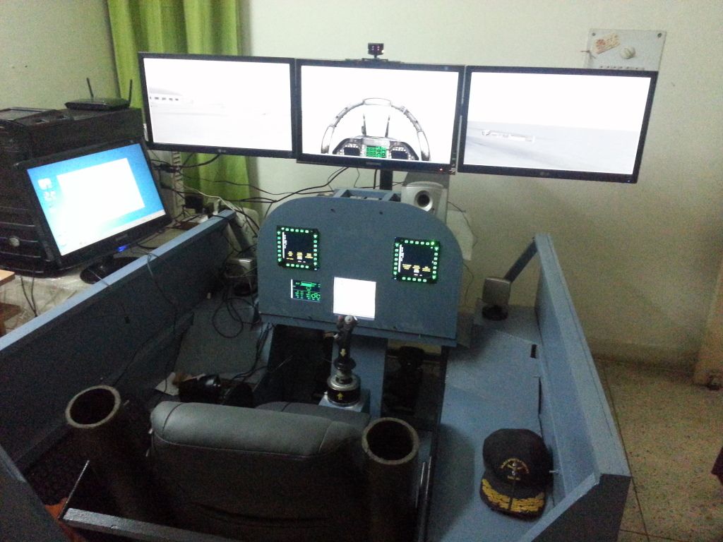
Firing up the Flight Simulator
Firing up the Flight Simulator.

Even with four displays undocked, and a pretty heavy scenery, the FPS (atleast on ground) is pretty steady between 25 - 35. The FPS is locked at 35 on my rig.

The 'Panel Positioner' needed a little tweaking also.
It worked like a charm in further tests.


The First Ride!!
Ha ha. She deserves the first ride, even if she has no clue how to start it up :)

Some of the pit dimensions didn't turn out how I had planned. But, it's looking good the way it is setup right now. All the labour intensive work is now done, hopefully. 

Now comes the 'interfacing' part. 

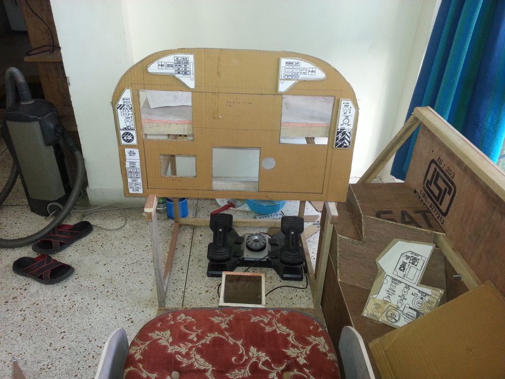
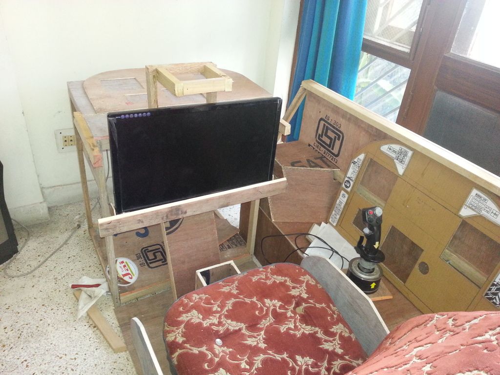
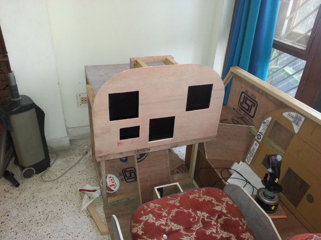
Over the coming weeks, I will be working on adding switches to the Left/Right consoles, Left/Right Side Panels (including Gear/Hook levers), fabricating a UFCP (don't like that big blank space between the L/R DDI's). In a departure from the real deal, I'm planning a touch screen for the MPCD also. Let's see how that pans out. Then, there is HUD brackets along with AoA indicator. The output annunciators will come last. 

And, there is getting all the cables routed nicely, add an instrument panel shield. Phew!!! And, I thought this was going to be a piece of cake.

15 December 2013

Sidewall Height Issue

Few friends, through PM/Chat have queried me, if the 'sidewalls of the pit aren't a shade too high'.

I thought I had checked the height out, before putting the blade to wood, but having more than one person raise this query, put me in a little doubt.

The base of the console's is 1 feet (12") from floor and top of the sidewall is 2.4 feet (30") from floor level. When seated on teh mock ejection seat of the pit, my shoulders jut out about 7" above the sidewalls. 

I had based my decision on sidewall height, based on a few pictures I had seen online (since I didn't have the precise dimensions with me).

So, it looks correct, when viewed from this perspective....

Or, this perspective...

But, NOT from this perspective...

I think, the open canopy in last picture takes away a few more inches from the sidewall height.....bummer.

I think I will complete the first version of the pit, and see how it goes.

Increasing the height would have posed a problem. Reducing it will only add a little more work.

Images courtesy of following webpages-

Image 1-  http://commons.wikimedia.org/wiki/File:US_Navy_050907-N-9277A-001_A_pilot_assigned_to_Air_Test_and_Evaluation_Squadron_Nine_(VX-9),_looks_out_the_canopy_of_his_F-A-18F_Super_Hornet_.jpg

Image 2-  http://commons.wikimedia.org/wiki/File:US_Navy_050407-N-0347W-002_An_F-A-18F_Super_Hornet_pilot,_assigned_to_the_Black_Knights_of_Strike_Fighter_Squadron_One_Five_Four_(VFA-154),_waits_with_Old_Glory_for_his_turn_to_be_launched_off_the_flight_deck_aboard_USS_Carl_Vi.jpg


Image 3-  http://ibnlive.in.com/photogallery/3323-2.html

Sanding and Primer Coat

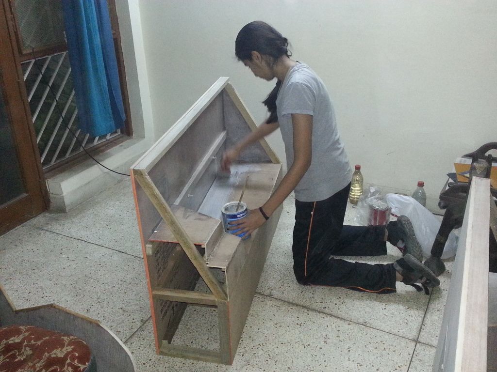
Finishing up the instrument panel facade and HUD bracket.


Daughter helping me out with application of wood primer
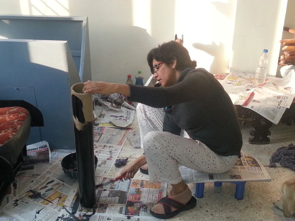
Wifey helping me out with painting the 'Ejector Tubes' of the Ejection Seat :)

End of the Day
Application of first coat of paint is complete. 
Need to let the paint dry for atleast a day, before I apply another coat. 

Will spend tomorrow, getting all my panel overlays sized up correctly in PhotoShop. 

Can't thank my family enough, for letting me carry on with my 'crazy' ideas and for even supporting me through it.