The only reason for this initial decision, taken more than two years back, was; 'I didn't think it possible for me to be able to build myself a home-built, working, fully collimated HUD'.
A lot has changed in these two years. Thanks to the experiments by folks like Baldrick (on Hornetpit forums), and my own experiments, I now know, I could have built one.
And, I eventually will.
But, in the present design of my cockpit, there is just no more real estate left, to include a working HUD.
It's just about midnight on a Sunday. As per my original plans, I was supposed to complete my pit today. As of Friday, the only thing left for me to do was, design and build an AoA gauge and complete the wiring for all the annunciators.
As I sat down to design the AoA gauge, I decided to build a mock up HUD bracket also. Two day's of weekend, were completely consumed by building this simple device.
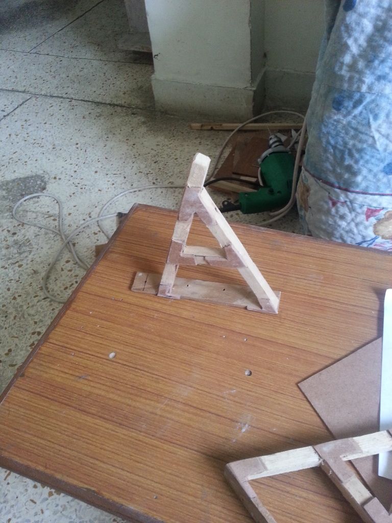 |
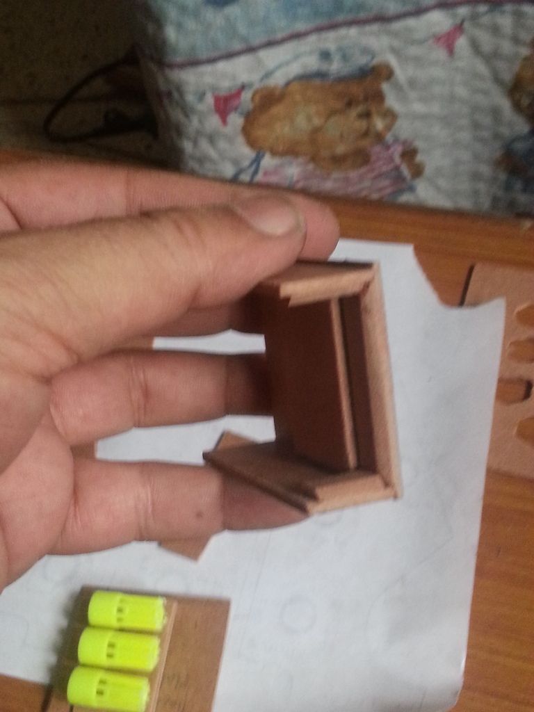
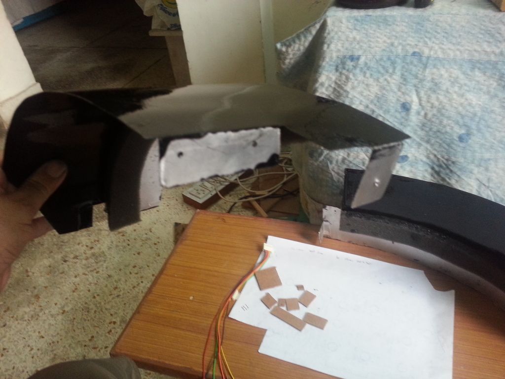
| Start of an 'abridged' HUD bracket. Pasted MDF cutouts at each joint for two reasons, it adds to the strength of the joint, and it also adds to the texture of the piece. This will look totally different, when it is filed, primed and painted. |

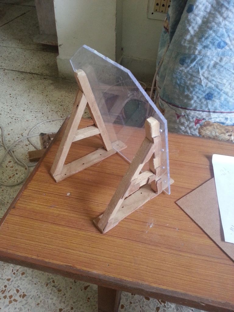 |
| Sizing it all up, with the combiner glass included |
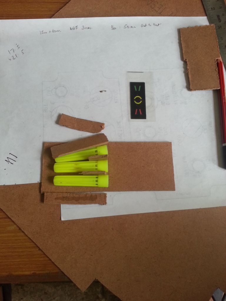 |
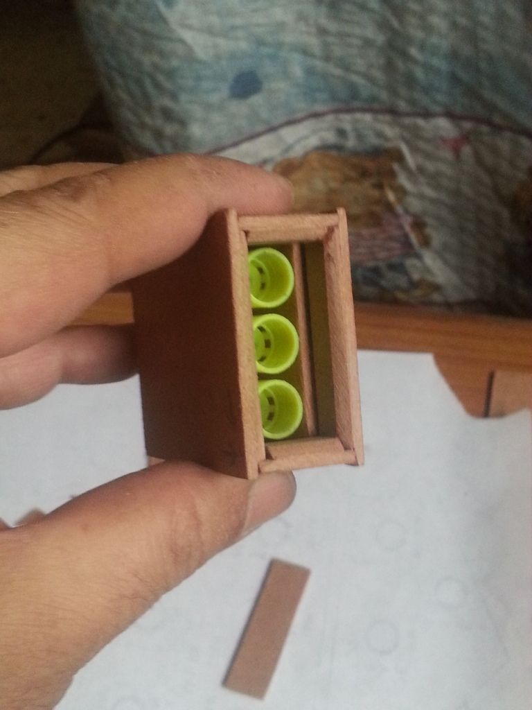
| Starting the build of AoA Gauge Sizing it all up. Taking measurements, planning the build. I decided to use the caps of disused sketch-pens of my daughter to make the LED mounts. These caps will ensure that the light of the respective LED stays confined and doesn't filter out to the other LED. Still need to figure out a way to block the very small holes near the base of the pen cap (seen towards the centre of the picture, facing right) |
 |
| Finalized my decision to go ahead with the use of pen caps. Cut them to the right size, and commenced the build. |
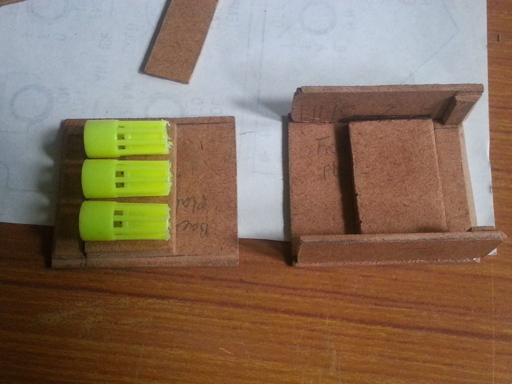 |
| The 'front' and the 'back' plate is now ready. I designed a correctly sized "groove" to accommodate a printout of AoA gauge markings on a transparency sheet. The measurements and eventual build is such that the front facia will correctly fit. |
 |
| Filing the finished the work piece |
 |
| Testing out the final fit, before I close it all up, and start to paint. I forgot to take a picture, but, I used the normal 'play dough' to seal the joints all around the pen caps. This positively ensures that no unnecessary light leaks out of the respective 'tube' |
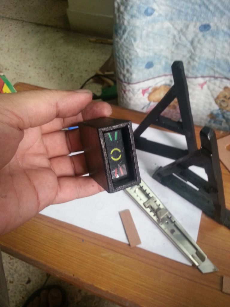 |
| Painted and all ready to be assembled. I felt very satisfied with the overall finish. It took really long to design and build this simple contraption. But, I'm glad I took the time. |
 |
| Assembled and all ready to be mounted in the pit The wiring will come next The bottle of play-dough, I mentioned previously, is visible in this picture. |
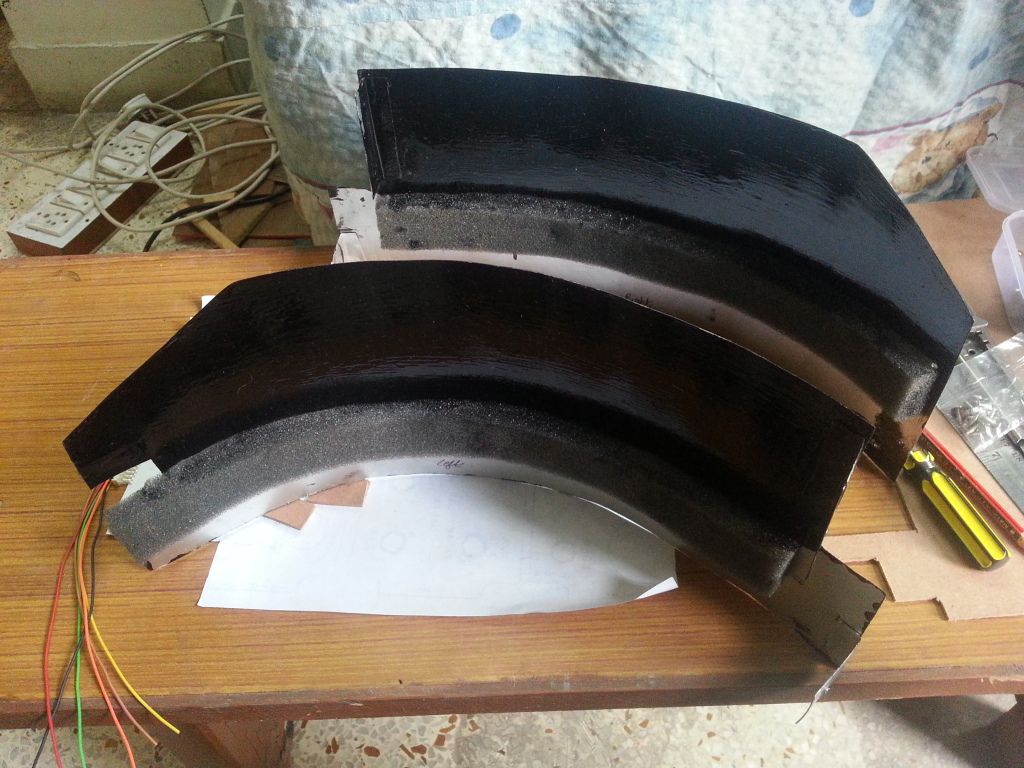 |
| Since the weekend was practically lost, just finishing up a simple piece, I decided to complete another remaining item. The left and right coaming panels. These will come on top of the Main Instrument Panel. Mark 'Wood' Killen, based on whose original design, the initial design of my pit was based, had done his coaming panels with plywood. Originally, that's how I had decided also. But, then, I decided to use sheet metal instead. I'm glad I did. Aluminium sheet metal is much easier to work with, compared to plywood, it also provides a better paint finish. Removal and installation of these panels is a bit intricate though. There is just no space to work in the pit anymore. |
 |
| I was trying to show the curved upper surface the paint finish in this picture, but the picture didn't come out as intended. |
Was very happy to see the whole cockpit come alive with all the lights.
Unfortunately, I was too beat to take any pictures.
Will post them, as I complete more of wiring during the week.
No comments:
Post a Comment