29 April 2014

Why do you build a cockpit

A question by an amused bystander, "Why would you build a home cockpit".

Answer by Baldrick, "Because, I can".

Baldrick, is another Rhino pit builder on 'Hornet Pit Builders' Forums, and is half way through an exemplary home pit build. I find the aforementioned quote by Baldrick, very simple, plain-speak, unassuming and truthful.

Over a period of last one year, I have been asked this very question by many friends and family, most of who (I'm sure) thought I had crossed over to the other side (of sanity). :)

Anyways, after a hectic weekend of trying to complete my pit, I wanted to complete the minor tidbits still left over in annunciator wiring. As luck would have it, I got delayed at work. Not to waste what little time I had today, I thought, I might as well calibrate my touch screen UFCP and other in-cockit displays. 

Was quite content with how it panned out, eventually. 

My digital camera is mostly in my daughter's custody, and I can never get my hands to it, when I need it in a hurry. So, most of my pictures get taken on my phone. The picture I took today, in less than ideal light, was not much to look at. So dabbed a bit with photobucket photo editing tools also. Just for fun. 


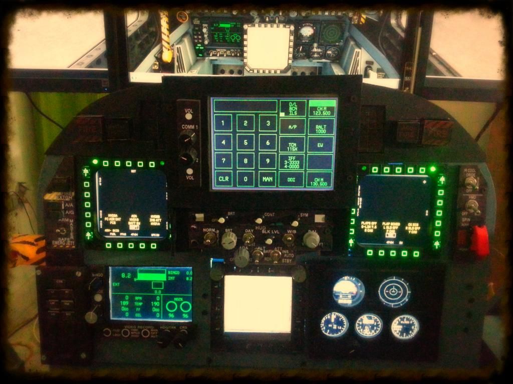
The real Rhino pit has spring loaded, two-position, clickable switches for HDG/CRS selectors. I had always thought that a rotary knob (a.k.a Altimeter Increment/Decrement Knob) to be a more ergonomic alternative. Don't mean to be rude to the folks at Boeing, but, I chose to make this modification in my pit. I embedded two 8 bit rotary encoders to drive the Heading and Course selector knobs on the EFD. 

Did a 4 point calibration and 25 point linearization on the touch screen of the UFCP (will post a video of the same sometime later), and now it works like a charm.

Spent an enjoyable half hour positioning all the 2D gauges. 

Am using the 'Panel Position' tool available on Avsim to position the undocked 2D panels across multiple monitors. It's an awesome tool. Instead of using the GUI method (physically dragging the panels across), I found that it's best to get into the config file and manually edit the values to derive a precise control over position of each panel. One can control the starting coordinates and height/width of each panel upto a pixel. Awesome!!!

28 April 2014

The cabling harnesses

I had planned to complete the cabling looms for all the in-cockpit indicators today. 

As far as cockpit wiring goes, I have tried to keep it as 'modular' as possible. My job necessitates frequent house changes, and it was an original design criteria to make my pit portable. I have designed and fabricated it so, (that) I can take it apart in a day. Putting it all together again, will take a little longer though.

Each of the sub-panels (Left/Right Lower Console, Left/Right Upper Console have their own micro-controllers/HID controllers and the Main Instrument Panel has two HID controllers (Leo Bodnar BBI-32 and BU083X boards).

All the 'control' wiring for each sub-panel is self-contained. Each panel  connects to the main cockpit through three connections, one for power another for USB, and one for all indicator/annunciator lights.

The layout of the wiring for each panel, has gone through a series of iterations. Each time, I had to completely take apart my old wiring, and redo it all over again. But, I think, I have now gotten it right. Just about.

A few pictures of the annunciators cable harnesses are posted below. It was a LOT of work.

The Phidget controller board supports 64 outputs, and I have used each one of those. That is a total of 128 pins to wire up. Of all the wiring tasks for this pit, this one took the cake, by a lot of margin.

I'm glad, it's finally done.

The harness for 'Caution Panel'
Will connect all 12 caution indicators on the panel.
The two 12 pin connectors are the interface between Left Upper Console Panel and the main pit

Harness for the Left Annunciator Panel on the Front Instrument Panel

Harness for the Right Annunciator Panel

Harness for the 'Select Jettison Panel' including Flaps/Gear Indicators
This harness doesn't incorporate the 12 pin connectors since it's a part of the main pit itself.
While taking apart the pit, all I need to do is slide out the pin connectors, which are just push fit.

All of them in one picture
Still need to make individual cable for the APU lamp, Gear Flasher and the Hook lamp. But, these are going to be individual cables with quick dismount fittings to interface. Plan to finish them tomorrow, after work. 

Will start mounting the cable harnesses during the week, and hope to finish it in the next weekend.

27 April 2014

Master Caution Panel

The plan for this weekend was to complete the "Master Caution Panel". 

The base material to fabricate the MCP is 2mm thick MDF
Printed out a copy of the front facia and used it for measurements of width & height.
Used the LED mounted on the PCB to assess the thickness of the panel
The first cut
The spacers are to 'box-in' the light from LED to the intended annunciator

Making sure it all 'fits-in' correctly, before I finalize the build.
It does.

The base structure complete, front facia complete.
Soldered the LEDs to the PCB and correct spacing.

Ran into a glitch. Though the back face of the MCP had holes drilled in to accommodate the LED leads going out, but when I was testing the fit, I noticed the holes were not aligned correctly. So, had to make a cut-out, so that the PCB could fit easily. It wasn't planned this way, but, eventually turned out okay.


Painted all the parts with acrylic quick dry paint, and assembled the unit. 
Tested out all the LEDs, again. 

The annunciator front plate is laser printed on a transparency paper. During my initial tests, I had seen that too much light shown through a transparency paper and the overall effect was not very pleasing to look at. An additional layer of a cream translucent plastic sheet was added behind the transparency paper, and LED spacing (depth) was increased a shade, the effect comes out as intended. 


Assembled the MCP on the Right Upper Console. 
Still have another day left in the weekend. Will use it to make the harness (cable loom) for the MCP, and the remaining switches of Right Upper Console.

I thought, the Right Upper Console was completed today. Only noticed it now, that I still need to make a BUNO identification plate, a switch guard for the Wing Fold Switch, and a Hook Light. 

Phew!!!!

This pit is never going to be complete.

20 April 2014

Random Pictures

Learning how to Solder
Making my own 24 pin connectors

Making a PCB with 4 push button tactile switches

Making a 'harness' for 40 light annunciators on the Main Instrument Panel


Rear view of the Main Instrument Panel
All digital inputs of one BBI-32 board are completely used up by the MPCD. There are no analog inputs on the BBI-32. The BU-0836X board (shown unconnected in this picture) has since been connected to the remaining digital/analog inputs on the MIP.  

Front View of partly finished Main Instrument Panel. 
Since this picture, the EFD has been completed. The UFCP has already been completed, as a separate "Strap On" module. The UFCP has it's own dedicated micro-controller built in (a Teensey 2.0++), so it doesn't need any interface with the MIP except get mounted here.

The 'Selective Jettison Panel' visible in bottom left of the picture, is a custom design. I have used 2mm thick MDF for all fabrication. LEDs and tactile switches are built in. Due to my choice of materials, the panel is about twice as large as the actual panel. It's totally functional. But, this is going to the first part that I will fabricate in metal, when I learn CNC routers/lathe work.


Re-designed Left/Right Lower Instrument Panels. 
I have used a different material this time around. The back panel is 5mm perspex, instead of 12.5mm perspex used earlier. The facia is now laser printed on special canvas. I had earlier printed it on a laminated photo paper, and wasn't very happy with the surface finish. This material also provides very pleasant back lighting capability. 

Getting there!!!!

It's been a while since I updated the blog.

It's not because, there hasn't been any progress with the pit. There has been. 
A lot of it.

But, because, I wasn't happy about posting the progress. 

I spent about an year, planning this build. Spent another couple of years, working out the intricacies involved, fine tuning my build decisions, and then purchasing and collecting parts. The actual build has now been under progress for a little less than six months. 

Till I started the build, I had absolutely no carpentry skills. I had never soldered a wire in my life. Had never flashed (programmed) a micro-controller. Had never designed an electrical/electronic circuit. All the preparation I did was a weekend of tuition's with a local carpentry shop, and then I went ahead and purchased my own tools, and commenced the build.

As the build progressed, I have noticed that my skills have generally improved, and finish quality of the 'pieces' is now much improved compared to my earlier attempts. At many places, I found that I could better design a part, compared to how I had fabricated it earlier (typically, the undercarriage lever mechanism, hook lever mechanism, the selective jettison rotary selector mechanism e.t.c). 

I could have actually finished my pit, a few months back. But, that's when, I began to take it apart and rebuild all the parts that I thought, I could build better. Consequently, both the Left and Right Lower Instrument Panels have been completely redesigned, re-fabricated and wired with a new circuit. Ditto for the pieces mentioned earlier. 

Also, I have been looking at work of some of the folks at 'Hornet Pits Forums' and have taken guidance in design of my pit. The designs some of these folks have put out are incredible. And all these are home pits, done by folks who do it as a hobby. Not by professionals. Awesome work guys. 

The fact that most of my pit is made/fabricated out of wood means that at some places, some parts don't "feel" realistic. Ideally, I should have built them using CNC routers/metal work. But, those are skills that I presently don't have. 

For the time being, I have decided to continue to finish the pit as originally planned, and call it Mk-1.

It's been too long that I have only been building, and in the past few months, haven't logged a single virtual flight hour. I need to get flying again. Soon.

Will take apart my pit again, and continue to rebuild it better and more realistic in subsequent marks/versions.