09 December 2013

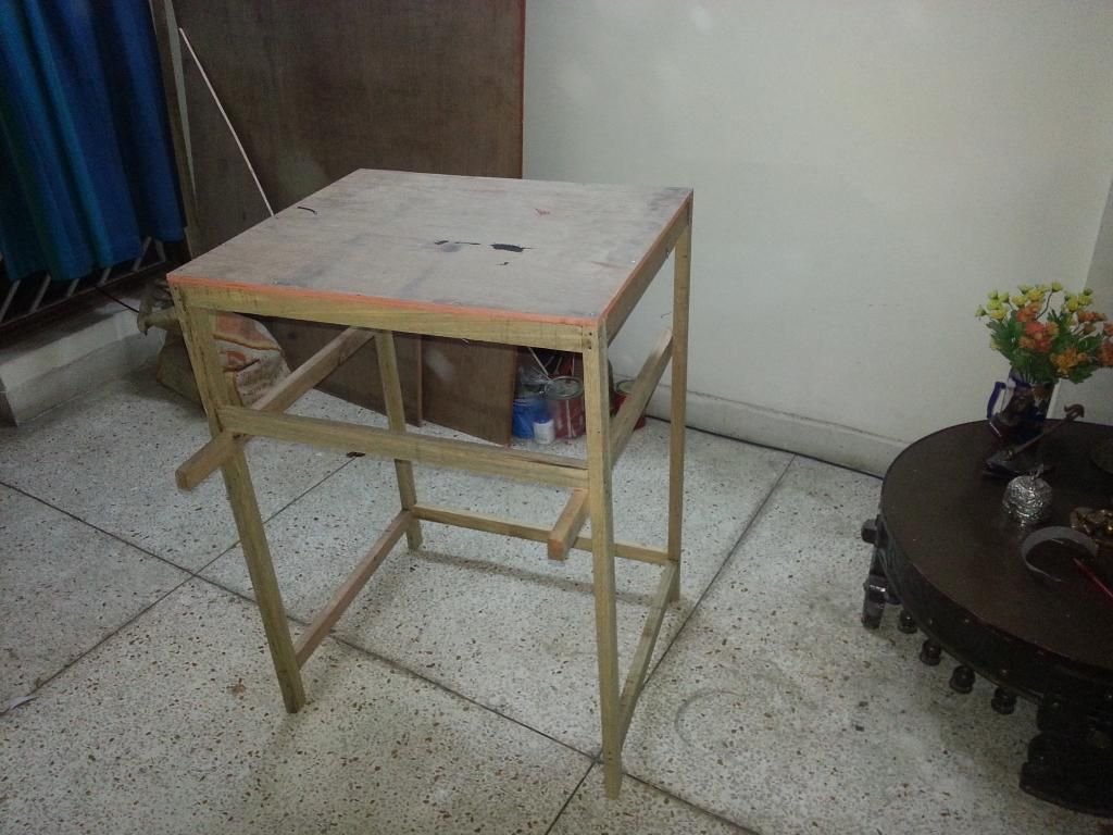
Pit Tub Build Commences

It's been a long time since I have been collecting parts, and generally preparing to start my pit build. 

Starting today, I have finally called out 'Commencing'!

I had already printed out cockpit drawings from the layout that Wood had sent to me, almost an year back. But, now that I had started to work, I realised that those drawings related to the F/A18-A version, and I had needed drawings for the "E" version. 

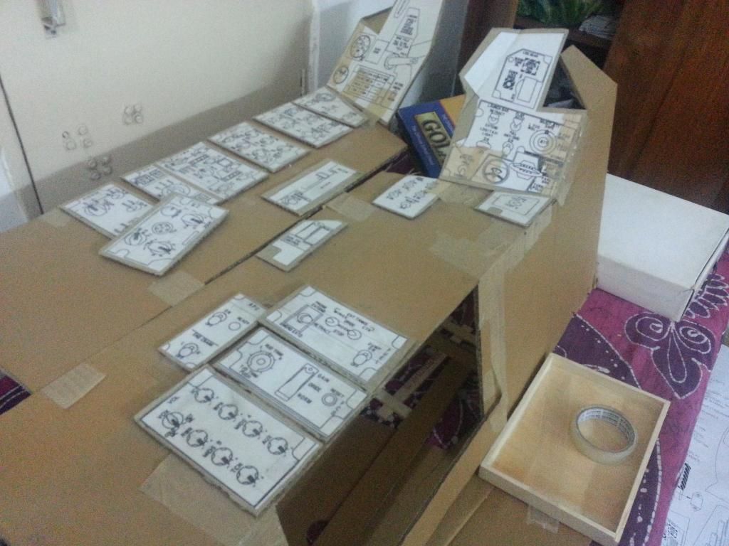
So, printed out the drawings from NATOPS document and pasted the A4 sheets to make one large cut-out.
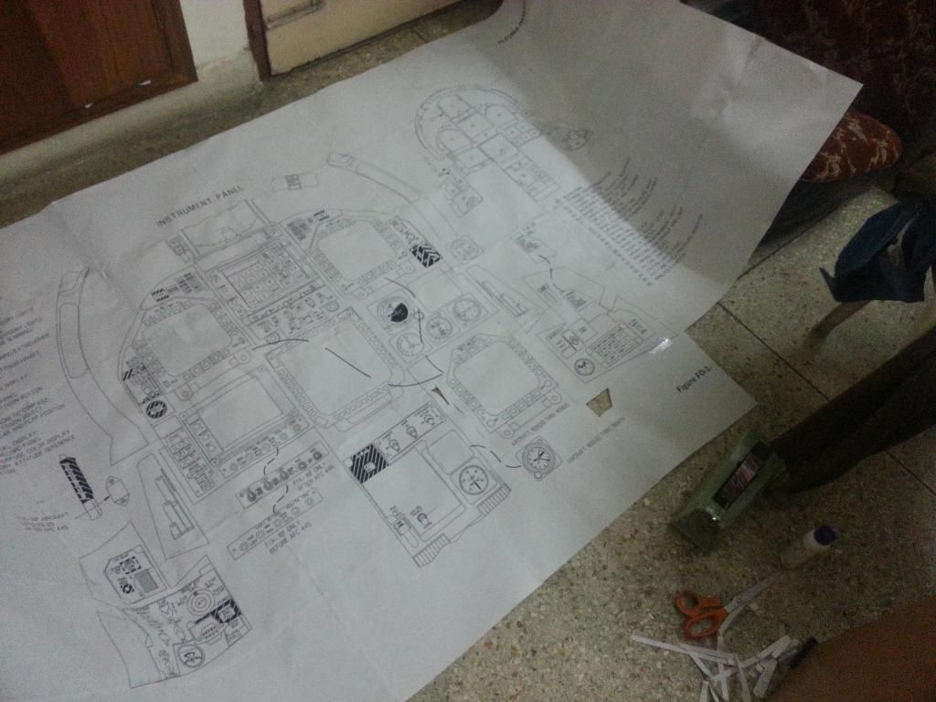
406% Expanded Printout of Cockpit Layout from NATOPS Manual 
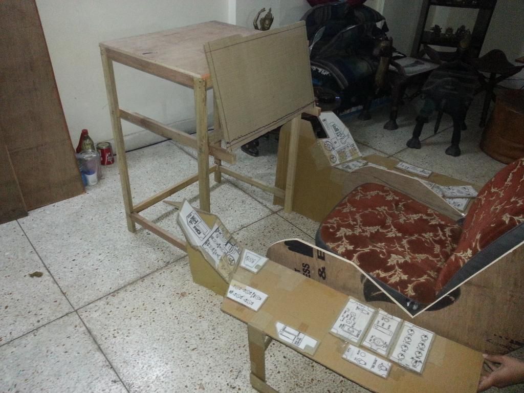
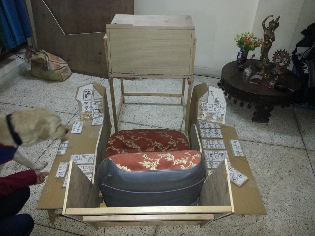
Mock Layout of Left/Right Consoles with Cardboard
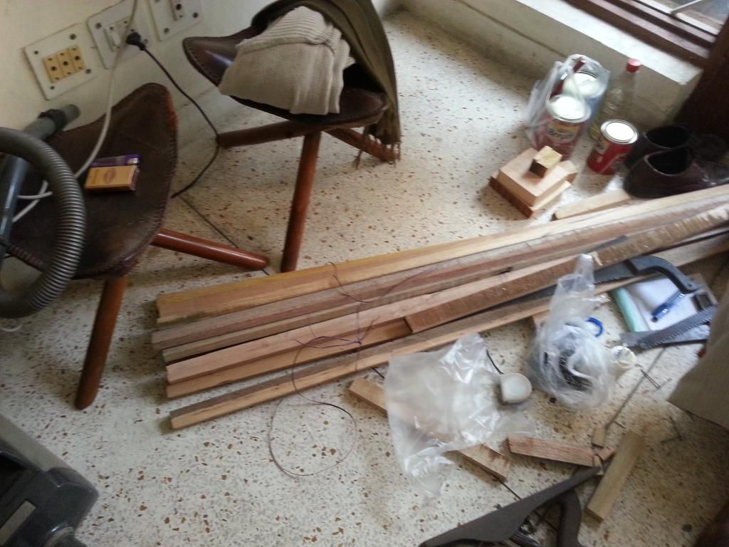
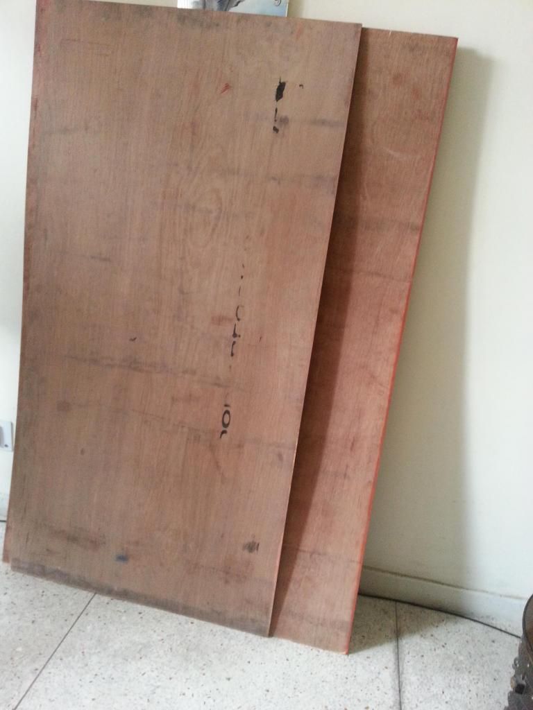
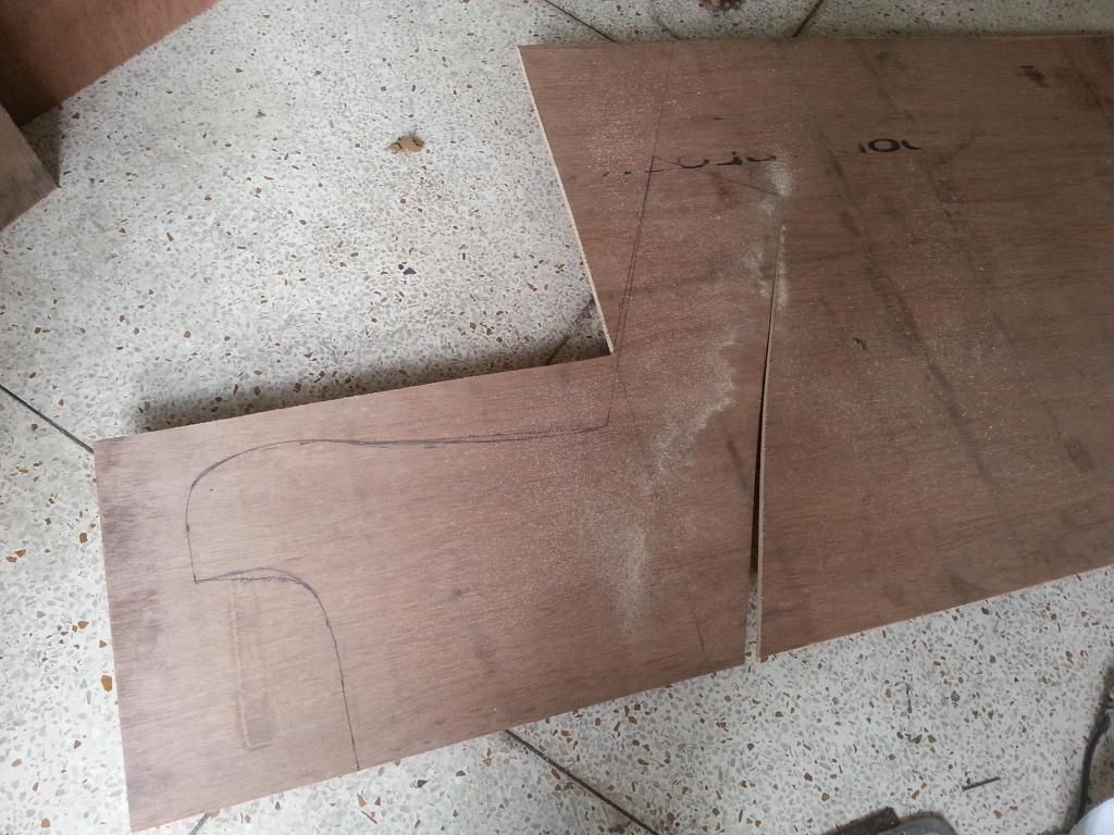
The Raw Material
The Raw Material - (Continued)
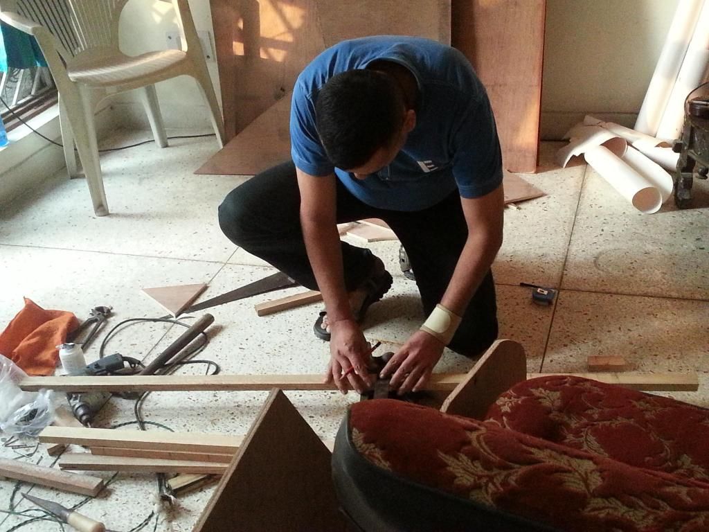
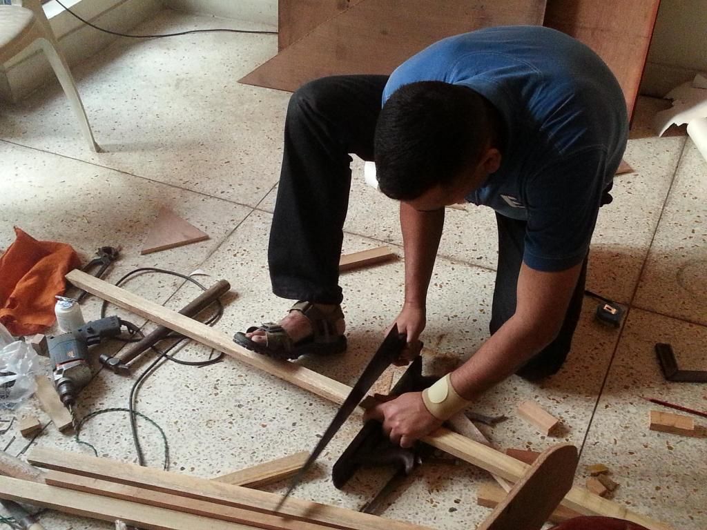
Get set and Go....


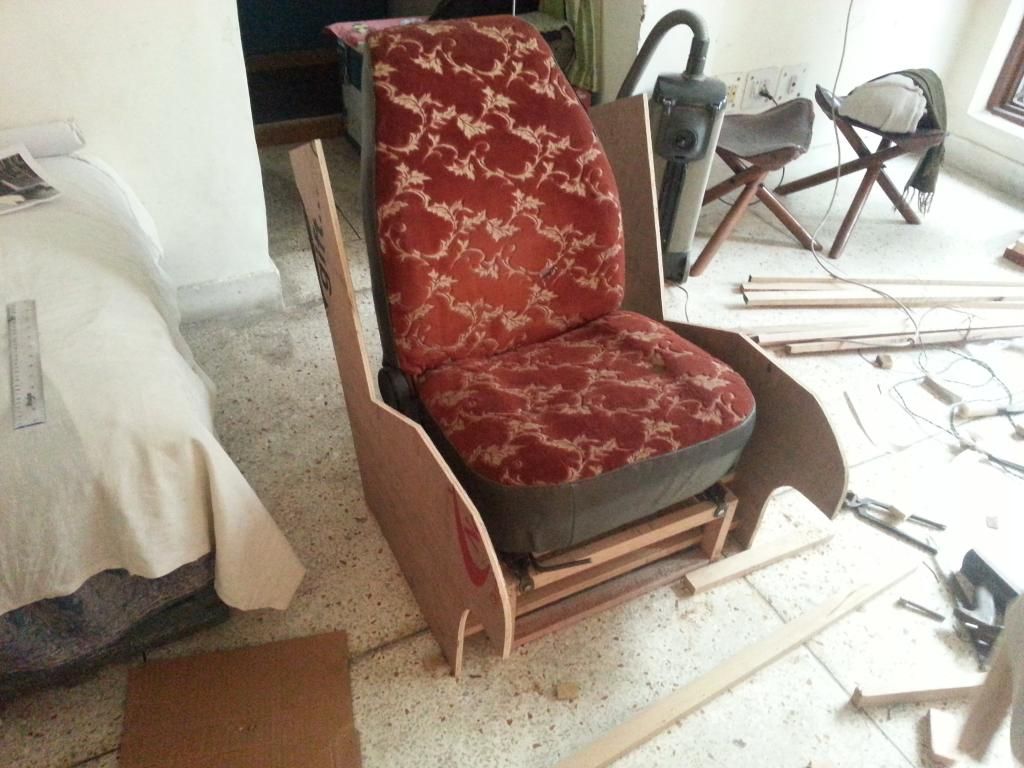
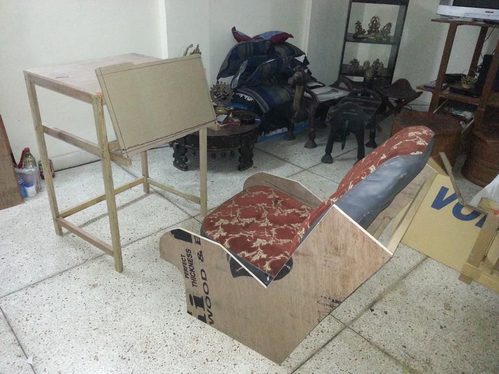
Ejection Seat Side Boards

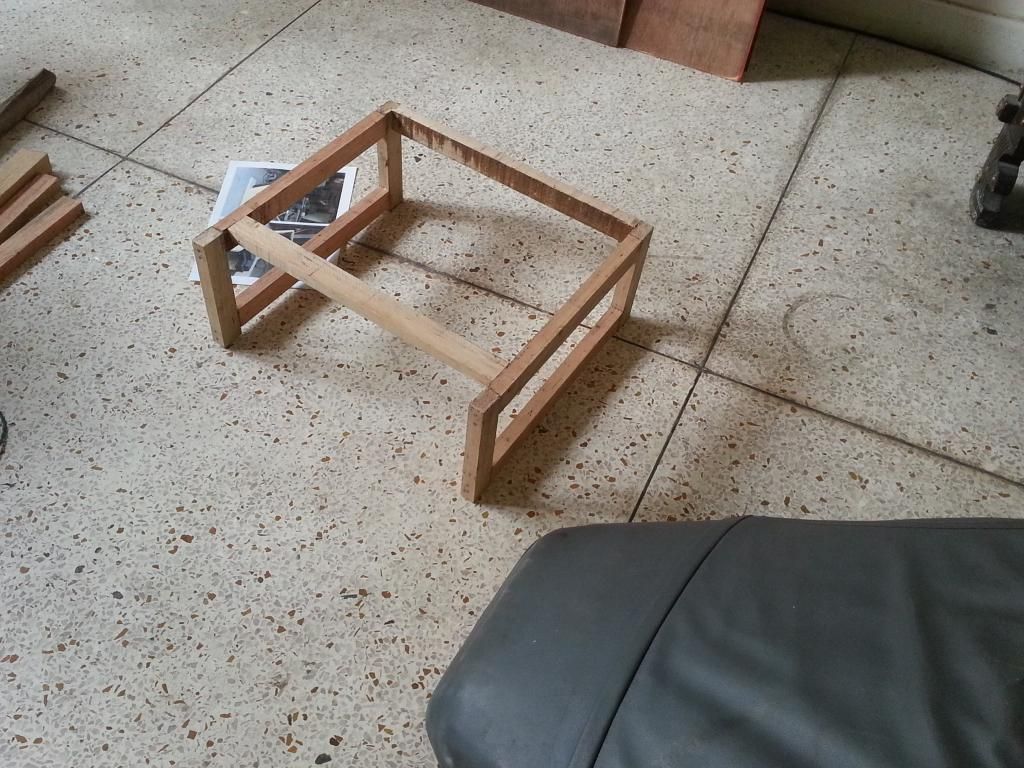
Bottom Chasis of Ejection Seat
Have built my Ejection Seat around a used car seat.
Advantage - I get to move my seat front/back based on need
The Front Frame
A triple monitor stand will come on top.
A 24" monitor will be mounted on front.
The Rudder Pedals will come underneath.
The Computer will be placed behind the frame.


Testing how it all comes together.
I am thinking, it should work?
My dog wanted to be the first to 'Pilot'.
I'll be damned if I let him!
Am pleased with the progress I was able to make between yesterday and today. 

Bit stuck up due certain commitments for next two days. Will recommence in two days from now. Hoping to get the basic woodwork (including primer/painting) done by Weekend. Will start with wiring up the panels next week. 


20 October 2013

Twerpy Rotary Knobs

It's been a while, since I documented any progress here. 

Reasons are many.....had to go through shifting my home and family due to work.....waiting and testing the new release of TacPac....and so on.

Ever since I had started this project, I had known that getting the correct (shape, size and color) rotary knobs is going to be a problem. 

Right Console Panel of VRS F/A-18E Rhino
I knew I will have to address this issue with 'Hook' and 'Landing Gear' control lever's also. Shapes of certain other switches (landing light switch, jettison knobs e.t.c) are also different from the switches I have managed to purchase commercially. 

I could purchase these switches internationally, but decided to consider that as an option, only if nothing else worked out.

Over the past few months, I had considered learning how to mold plastic at home. After a lot of reading, I finally decided to try and carve myself some switches out of wood and experiment how that pans out. Will take a final call, after completing my experiments.

Over the last couple of weeks, purchased myself wood carving knife chisel set and a diamond needle files set for carving out some wood. Both the tools were purchased off ebay.
Wood Workers Tool Knife Chisel 12 Pc Set

Diamond Needle File Set

With the tools in place, I experimented with my first rotary knob. I chose a sample which was neither too easy, nor too hard.
The Rough Stock

The First Cut (is actually the deepest)

Piece is shaping up now

Filing the "Piece"

Almost Done
Painted and Finished

How it compares

It was a good weekend. Finally made (a little) progress.

The knob has come out quite okay, though it's still not finished to the way I would like to accomplish. But, this is the first time I have touched wood and tools to work on wood. For a first time attempt, I'm smiling :)

As I find some more time, I will practice with a few more pieces. 

The texture, weight and feel of wooden rotary knobs is just about right. They take a long time carving, but it's turning out to be very cheap product to make.  


19 May 2013

AoA Indexer

If  a picture is worth a thousand words and a video is worth a thousand pictures, here's a million words....

Click here to View


30 April 2013

Uchi has a cat, ohh (B)Rat

My Phidget LED 64 - Advanced board had arrived a couple of days back.

As I indicated elsewhere, configuring my 'inputs' is now, no longer a concern for me. There are multiple options already available, and with Tripod's SuperScript Ver 2.00 almost on its final iteration, mostly, I'm going to use that tool for all input functions. 

Did a little testing with my Phidget board today.

Unpacked the board, and powered it up. Connected two green LEDs on Pin 0 & 1. And fired up the Phidget configuration utility. The utility detected the board immediately. Configured the LED voltages and current values and voila, the LEDs lit up bright and shiny. 


Fired up the FS2Phidgets utility developed by Alan from "MyCockpit.Org".

While FS2P detects my board correctly, but, despite spending many hours trying to debug, I'm not able to configure the board. The LEDs therefore continue to glow unencumbered by my efforts.

I now know what I need to do for next few days.

Read. A lot.

..and fix this (B)rat.

Tripod's SuperScript Ver 2.00

Tripod has been burning a lot of midnight oil, just to get the SuperScript Ver 2.00 up and running. Ver 2.00 of the script is now 'event driven' and is supposedly more efficient script. 

Over the last couple of weeks, was beta testing a developmental script for Tripod. The script is appropriately called as 'SuperCartridge' is intended to add a 'Data Cartridge' functionality to the Super-Bug. Al Rosenberg, as always, is the technical expert on the correctness of scripts compliance with real world procedures. My job was primarily to test the script and just see if my computer doesn't blow up. The SuperCartridge is coming along very nicely, and when complete this is going to considerably add to the overall F/A-18E experience. 

 Yesterday night, Tripod sent me an advance copy of SuperScript Ver 2.00. Spent a large part of yesterday night looking at the documentation. This version provides a single point interface for both input and output functions. 

Even though, this was the first time, I was looking at the documentation Tripod has created, I instinctively knew, this script is a 'winner'. I knew, I'm going to use it for all my 'input' functions. I don't even feel the need to test it. Having looked at this documentation, I know it will work.

My only concern now remains, configuration of flight sim outputs, to drive my LEDs.

While Tripod's script also provides output functionality, but, it's primarily coded in LUA. I have already committed myself to using output boards from Phidget, and these boards do not directly interface with LUA. They do however interface with FSUIPC. 

Need to find a little more time, and learn how to mate Tripod's script with my boards using FSUIPC.


13 April 2013

Phidgets

Past few months, work has been a little more hectic than usual.  What little free time (if any) was available, was spent with flying FSX. The pit build therefore has suffered since then. 

Starting mid-May, my work takes me to a different city. Shifting my house, and getting setup at new place, will now take priority over everything else. Till end-June, I don't see this project progressing any further.

In the meanwhile, I'm more than ever convinced that, while FSUINO and Arduino are good, but they won't work for me. In the meanwhile, I have done a bit of testing with 'Phidgets' and this looks like (for me) a better implementation of output scripts. These boards interface with FSX easily using FS2Phidget script by Alan. The script can be downloaded from mycockpit.org

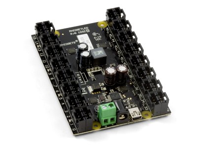
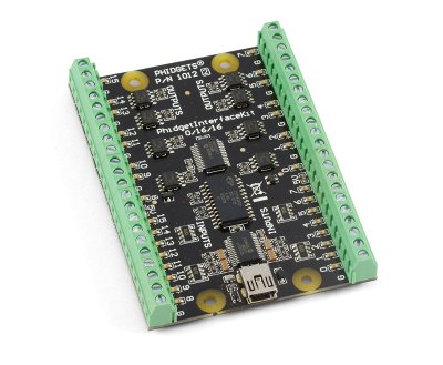
Just ordered myself a Phidget LED-64 Advanced board and Phidget Interface Kit (0/16/16).

Phidget LED-64 Advanced

Phidget Interface Kit 0/16/16
While the LED board is a necessity, the interface kit is a bit of an overkill. For one, it provides with ability to add another 16 inputs, but the reason for my choice was its 16 digital outputs. Each output is rated for 200 milli-ohms and 2 Amps of current per channel and 30VDC voltage. While I can drive 64 LEDs with the LED board, each output channel on that board is only rated for a max of 10mA current.

Some indicators in the pit (like Master Caution, Fire Warning Lights, for example) are very big and bright annunciators. With the LED board, I didn't have enough current carrying capacity available to drive more powerful lights. With this interface kit, I will be able to overcome that limitation. Due to better current/voltage handling capacity of this board, eventually, if I ever decide to do that, I could also use these channels to drive servo's (a.k.a custom cockpit instruments like battery gauge, hydraulic pressure gauge e.t.c, or rudimentary motion control).

With this purchase, I have now collected about everything I will need for the build, with the exception of various cockpit knobs. Those will be a tough cookie to source. But, we will cross that bridge when we reach it. 

In case I get stuck, my teen daughter is doing a research of her own. She has been collecting anything that remotely looks like a knob (fan regulator switches, broken rotary knobs from old electrical appliances, knobs sealing plastic bottles, including toothpaste tubes, shaving cream tubes and the like). She is confident, with a little molding using dried paper paste, plastic glue and color, she will be able to mold shapes that will look like knobs for me. Gotta love daughters.  


05 January 2013

Touch Monitor Kit

In what ever little time I get these days, I have been working on a 'card board' mock up of the pit. The idea being, to get a hang of sizes of various panels I will need to fabricate, and to identify cabling requirements for the I/O boards. Shall post pictures of the mock up pit in my next post.

Had originally decided to use my 24" monitor as the primary display to run my L/R DDIs, UFCP and also the MPCD.

While working on the mock up pit, I realized that 24" monitor doesn't have adequate real estate to accommodate all four instrument panels. 

So decided to order myself another 8" touch panel along with touch screen to fabricate the UFCP (Up Front Control Panel). 

Instead of purchasing a ready-made monitor, I also decided to purchase a 'kit'. A kit will provide me with flexibility to fabricate my own UFCP.

The 'kit' arrived a couple of days back.


Boxed kit as it arrived
During the ordering process, I had indicated to the vendor that I need this kit in a little hurry. He made sure the complete postal department understood the need for V(ery).V(ery).Most Urgent need.

Opening the box

I had ordered a 'power adaptor' separately, I see that they have remembered to pack it along

Unpacking the 'board'

'USB Touch Controller' board on the left side and touch monitor packed on the right side

A close up shot, to document any damages during transit. The 'stand-by' micro-switch button is damaged. But, it's nothing that I can't fix myself


Driver CD is enclosed, also


 USB touch controller board

 
Complete assembly. The 'ribbon' cables are notoriously fickle and need to be handled VERY carefully, lest they get damaged. VGA display connector (blue) is visible in the left-centre of the display controller board.


 Haven't had the time to test the assembly yet. Other than the damaged micro-switch, rest of the 'kit' looks in good shape. I don't need those display controls for my pit, but, if they are ever needed, I will be able to replace/repair this microswitch myself. 

The size of the monitor is just about correct to make a 'handsome' UFCP. 

I'm now excited to rig this up. 

If only I can get a little more time on my hand.